Robotic Dross Removal Is The Future
Millennium Steel, June 2022
5
Millennium Steel, June 2022
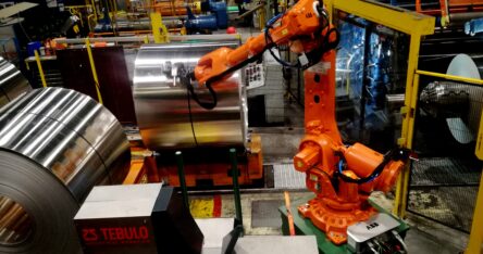
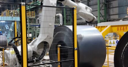
“A substantially higher production speed, as well as printing a marking of more characters on the flat and rounded sides of extremely hot rolls of steel, in less time”. Thus, the demands imposed by China’s leading steel producer when ordering the latest marker robot for their hot strip mill from Dutch manufacturing company, Tebulo Industrial Robotics. Or, in short: “Substantially improve the cycle time of our hot strip mill.” In this article, Hans Spaans, Technology Director of Tebulo Industrial Robotics, explains how he met this challenge in a country supplying 50% of the world’s total steel production.
With considerable speed, approximately 60 glowing hot rolls of steel (800° C), weighing 20 to 30 tons each are passing through, with their ‘eye to the sky’, on the ‘walking beam’ in the Chinese hot strip mill. Positioned beside the ‘walking beam’ is Tebulo Industrial Robotics’ latest marker robot. Within the traceability context, this robot applies a unique ID number to each of the rolls. For several decades and to the fullest customer satisfaction, Tebulo Industrial Robotics delivered marker robots to the leading Chinese steel manufacturer, annually producing 21 million tons of steel.
For over 20 years, the above production line had operated with a Tebulo marker robot. Spaans explains: “However, the robot had reached its technological end of life and needed to be replaced, as spare parts were no longer available. So this was the main reason for ordering a new marker robot.”
Process
One by one, the robot prints markings on passing rolls, which appears simple. Yet, in practice it turns out to be a considerable technological challenge. Namely, on this production line, the exact position per roll is not defined: It is always an approximate position. Consequently there may be considerable variations in a roll’s position. Due to the extremely high temperatures and slight inaccuracies in the line’s drive system, the rolls of steel are not accurately positioned. As soon as the roll in need of marking stops, the robot must first detect where the marking should be placed on the roll’s side, as well as the roll’s exact position and height. In order to establish this, first a procedure to determine the accurate measurements must be carried out. Successfully performing the procedure constituted a major technological challenge, since it is all very time-critical.
Time
The cycle time per roll amounts to 60 seconds. Per roll, only 25 seconds are available for the application of the marking and the measuring procedure, while merely 15 seconds are utilized for the actual measuring. In other words, the unique ID number has to be applied in the 10 remaining seconds. Spaans explains: “This was hardly feasible for the old robot, let alone with the new one. The standard for the latest marker robot was, namely, that it had to have the capability to maximally apply 25 characters at a time. On average, the application of 1 character takes 1.2 seconds. The smaller characters still take 1 second per character. Once the walking beam stands still, the marking is applied. The line comes available as soon as the robot finishes its procedure. While intending to solve these technological challenges, the producer intended to increase line performance as well. In short: More had to be accomplished in less time. So we needed to find a different, smart solution.”
Previously
In the old process, the line control system determined when the rolls of steel were stopped. There were no line data, speed and position data available. So the robot’s controller received a start signal from the line controller as soon as the line stopped. Next, the robot controller received the printable data. Before the marking could be applied to the roll of steel, the robot arm moved towards the steel roll in order to measure the diameter, position and height of the roll in a fixed pattern. Next, based on all of these data, the controller could plot the robot’s exact trajectory needed for the application of the marking’s received number of characters. Spaans explains: “Elaborating upon the old system, we have sought for a way to gain time somewhere. The idea emerged to optimize the measuring cycle by conducting it while the rolls of steel were in transport. Also, whenever feasible, process time could be considerably shortened by performing various measurements simultaneously, instead of one by one.”
Measuring Process
The measuring process consists of a combination of a distance laser and synchronization of line transport. Every 5 ms, the laser detects each roll’s contours by performing a distance measurement on the passing roll from a fixed position. The speed at which a steel roll passes is determined by accurately measuring the line movement with the assistance of the line transport sensors. By combining data derived from both measurements, the respective roll’s contours may be determined, as well as its exact stop position. Next, these data are sent to the robot controller which combines these data with the fixed, known distance to the walking beam, in order to calculate the roll’s position and particularly the location of the arch on which the marking needs to be applied. Moreover, the known information is that the rolls are accurately positioned within +/- 200 mm. The rolls are perpendicularly placed on the line by means of a tilting system with an allowable positioning accuracy of +/- 150 mm. In other words, based on the available information, the robot’s controller easily plots the exact trajectory in which the marking needs to be applied. No additional measuring is required in the described approach, aside from the roll-height measurement, saving approximately 10 seconds per roll. When asked whether the height measurement might also be included in one pass, Spaans responds: “No, a height measuring process is necessary under all circumstances. This is because not all rolls of steel are identical, while the marking position, as seen from the top down, must always be identical. The height measurement also helps to determine whether the roll has a case of telescoping. This measurement performed on the roll’s flat side is a tested and approved measuring approach. In a case of excessive telescoping the marking is only printed on the roll’s rounded side.
Single Nozzle
On average, every 3 to 6 weeks, during a regular maintenance stop, the robot receives any necessary maintenance. If the rollers of the hot strip mill have to be replaced, then the line with the rolls of steel needs to be emptied. Consequently, the line transport speed changes. In the controller’s new configuration, this does not at all impact measurement accuracy. Just as previously, the customer decided again for a single nozzle for the latest marker robot. A seven-nozzle dot matrix is faster in applying a marking. However, the single-nozzle design is much less sensitive to pollution within a hot environment, so it has a better performance output than the dot matrix. The white paint utilised for the marking’s application was fully developed in-house by Tebulo Industrial Robotics. The paint can easily be refilled while the robot is in operation, since the paint supply system sits outside the safety fence surrounding the robot.
Finally
Concluding, Spaans says: “Meanwhile, Tebulo Industrial Robotics has placed several marker robots, as described above, in hot strip mills worldwide. We were able to accomplish a considerable time savings per roll, particularly by integrating data from line and robot control in conjunction with parallel implementation of various measurements. This benefits the line’s eventual performance as well as TCO.”
27 January 2023 by Eize de Vries, Windpower Monthly
This year, the best innovation award is shared by two very different ways to standardise wind turbine production for much larger volumes.
Ground-breaking Vestas modularised nacelle concept
Vestas’ containerised and modularised nacelle concept is a multi-purpose structure with container-specific add-on features for lifting, transportation and storage. It also reduces the turbine’s carbon footprint by turning nacelles into self-contained transportable modules.
The out-of-the-box concept aims for full value chain simplication, from component sourcing to manufacture, transportation, installation and lifetime upkeep. All are challenged by growing nacelle dimensions with scale, plus envisaged huge future leaps in turbine volumes.
The modularised nacelle concept was introduced with the enhanced EnVentus V162-6.8 MW, involving the switch from a single nacelle to a split compartmentalised arrangement with reduced dimensions. The main elements are the central nacelle and single “click-on” side compartment, which is effectively a modular power unit containing converters and the MW-transformer (below). A second (optional) service side-compartment incorporating a foldable crane can be hoisted up and attached to the other nacelle side, again via standardised lock-pin interface connections.
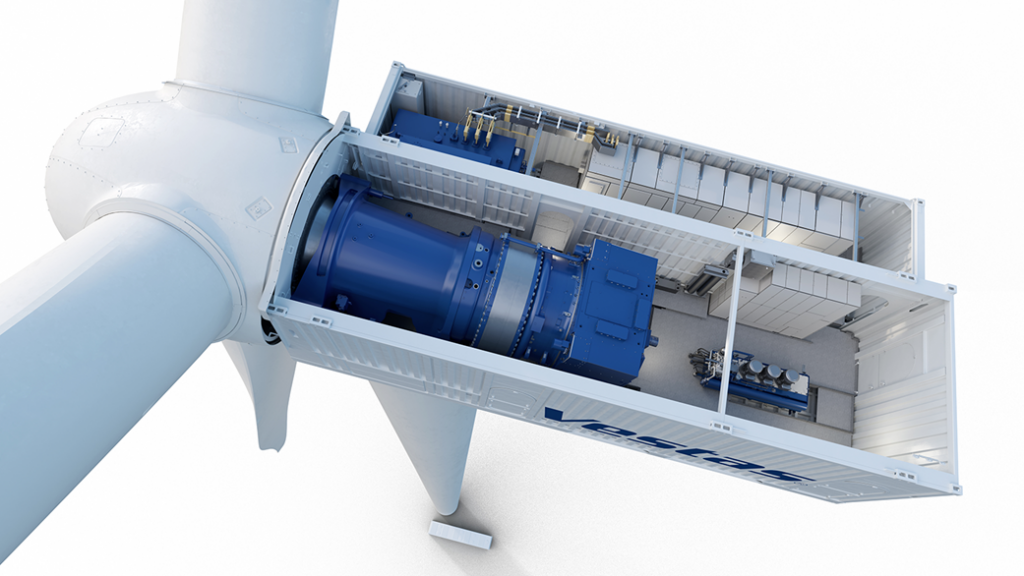
The V236-15.0 MW features two such modular power units, now permanently mounted, plus a separate service crane arrangement.
The modularised architecture creates flexible platforms from reusable building blocks with clearly defined physical boundaries, enabling platform synergies regarding design, testing, validation and long-term asset upkeep across onshore and offshore applications.
The V236-15.0 MW prototype was installed in late 2022. The EnVentus V162-6.8 MW prototype with modularised nacelle will follow in 2023, while a date for the EnVentus V172-7.2 MW has not been disclosed yet.
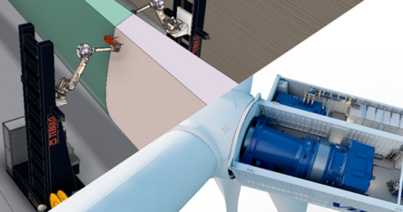
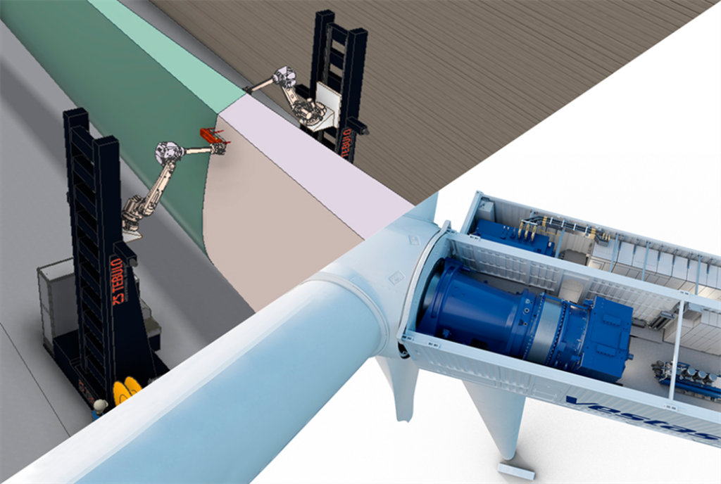
TebuloRobotics AGV solution for the production of large blades
Dutch hi-tech industry solutions specialist TebuloRobotics conducted its first robotised blade-spraying demonstration in early 2021, which it says generated overwhelming (wind) industry responses.
The technology concept is based on a multi-purpose in-house autonomous guided vehicle (AGV) or advanced tool carrier, deployable to autonomously perform multiple pre-determined new or repetitive sequential tasks, including during rotor blade manufacture.
This AGV has four electrically powered 360-degree rotatable wheels, allowing unrestricted precision vehicle movement in all directions, enabled by cutting-edge external guided motion technology. This allows AGVs to autonomously enter a given production hall, move towards a pre-selected blade and start performing a specific, predetermined task. It follows a blade’s complex three-dimensional shapes and curvatures without requiring detailed product-specific dimensioning or hard robot programming.
Multiple deployment opportunities explored with industry partners include blade deburring after mould removal, surface grinding and coating, vortex-generator and lighting-receptor placement, blade-root grinding and studs placement, and non-destructive digital blade-inspections including ultrasonic scanning.
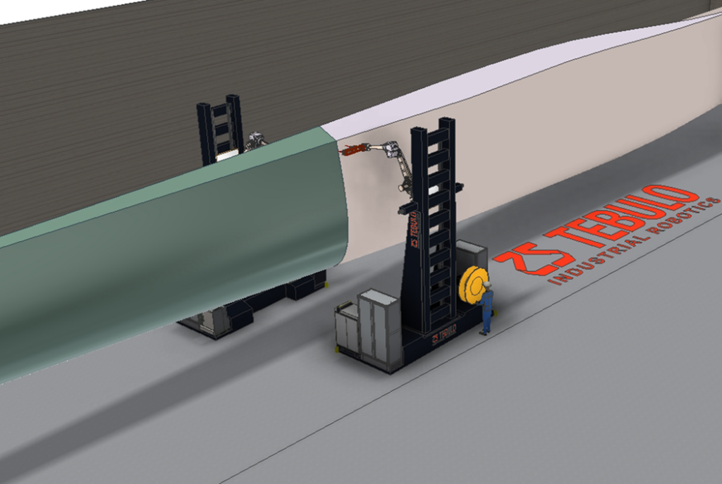
With blades becoming ever longer and thus also getting wider, a specific focus area has been to develop fast, high-quality automated coating to replace increasingly time-consuming and resource-intensive current manual practices. The total blade surface area is estimated to be in the 1,000-1,400m2 range for 14-15MW flagship offshore turbines with 220–236m rotors. TebuloRobotics is working on two alternative robotised blade-coating solutions: with paint rollers and precision-spraying.
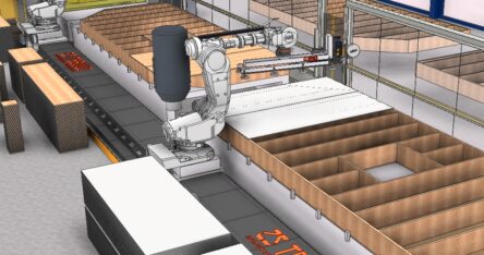
According to the forecasts, 1 million houses need to be built up to 2030 in order to meet the housing shortage in the Netherlands. In response, Vadeko commissioned system integrator Tebulo Industrial Robotics to develop a robot production line with 2 robots for the production of prefabricated house wall panels. With this solution, the company is able to save 31 minutes production time per element.
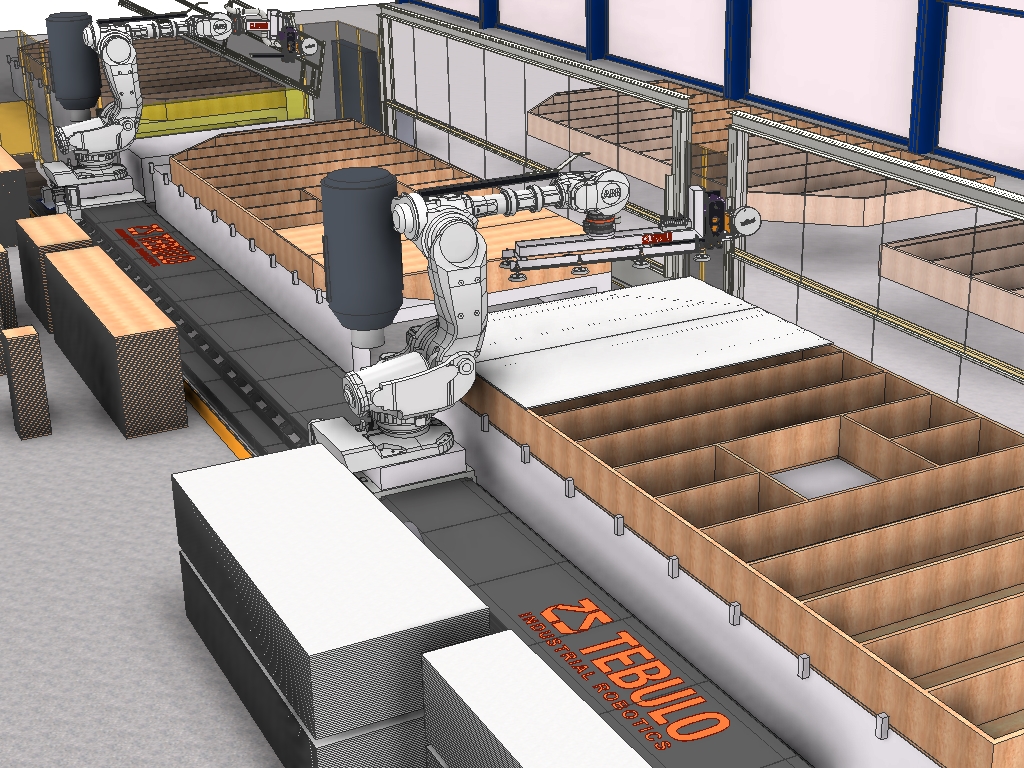
Vadeko, a renowned supplier of Prefabricated House Wall Panels for all large construction companies in the Netherlands, produces prefabricated inner and outer wall segments of up to 8-metre-long hinged roofs and floors. For this purpose, Tebulo Industrial Robotics develops a new production line with 2 collaborating robots which move along a 20-metre-long ‘track’. Currently, such so-called TFC (Timber Frame Construction) elements are still largely produced by hand.
Saving Time
The production of a single complete wall element currently requires the combined efforts of 2 FTUs for 40 minutes. By integrating the robot line, the same wall element may now be produced in as little as 9 minutes, through a unique interplay between man and robot. How exactly does the new system work?
Unique Interplay
At the beginning of the production line, 10 to 36 cm thick timber frames for various HSB elements are manually joined by an operator. However, once the timber frame is ready, it is quickly pushed to the robot line and the first robot applies the cladding, nailing it to the frame on one of the two sides. The second robot ensures that the desired window and door openings are milled out in the right spot. The wooden frame is then rotated 180 degrees in one movement on the inversion table which is part of the production line, so that the cladding side is underneath. An operator then manually installs the cabling (fibre optic, electronic cables, etc.) and insulation, after which the same robots, a little further down the line, again carry out the required cladding and milling work, this time on the reverse side. The milled residual materials are removed from the production line by the unique interaction of both robots and then transferred to a ready-to-use waste container. It is interesting to note that both robots have a 325 kg payload.
Installation
On schedule, the 20-metre-long track was successfully completed and installed by Tebulo Industrial Robotics. The next step is to install the 1st robot followed in early 2023 by the 2nd robot. According to Tebulo, the greatest challenge for putting this robot line into operation is the meticulous configuration of the software. Contrary to a human being, a robot does not have any hand-eye-coordination. Moreover, programming the interaction between the two robots while making sure that they do not crash into each other, is extremely complex and requires much expertise.
In cooperation with Cojafex, Tebulo Industrial Robotics is developing a robot with induction technology and ‘external guided motion’ software for heat treatment of multiple bends in steel pipes (i.e. ‘pipe spool’) up to a diameter 20”. The tempering process reduces the stress caused within the bends of the pipe spools.
The idea of deploying induction technology for this new robot system was launched by Cojafex, who utilized this for many years. Subsequently, Tebulo Industrial Robotics combined this technology with their many years of experience in the field of robotics and EGM software. Application of EGM software enables the system to easily follow any steel pipe with bends (i.e. ‘pipe spool’), without the need for complex robot programming. Based on the shape detected by the robot, the heat treatment will be done within the set parameters The system creates a measuring report that may be used for quality control purposes later on.
Before
Traditionally, heat treatment after a bending process on bends is done in an oven at approx. 600 °C, followed by cooling them. The new robot system is considerably better for the environment and leads to substantially lower energy costs. Moreover, by using this technology deformation of the end pieces (tangents) can be avoided.
Clamping System
The new robotic system is best compared to a so-called nerve spiral, a widely known game. Over a 9-meter long ‘‘track‘’, the robot moves up and down from one end of the steel pipe to the other. In this system, the 3- to 5-meter long pipe spool is always clamped at one end in a hydraulic clamping system. In the 0 position, the robot is positioned with the induction ring against the clamping system. From there, the robot scans the shape of the bend/spool. The system is provided with a clamping system on either side of the robot ‘‘track‘’. This enables the robot to work on one side, while the operator puts a new ‘‘spool‘’ at the free clamp.
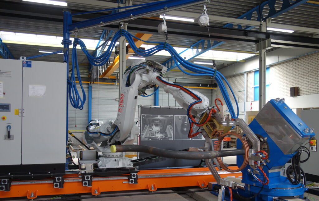
Heating Process
Once the contours are scanned, the robot travels the same trajectory again while heat treating the bends in the spool. As soon as the robot detects a bend on its trajectory the induction ring the pipe automatically heated to around 600 °C. The (heare treatment) process speed is approximately 1 mm per sec. to allow a good heat distribution in the material. As soon as the robot reaches the pipe’s straight part again, induction heating is fully automatically switched off. Once the process is completed, the pipe spool is cooled down, prior to its removal from the clamp, while the robot returns to its 0 position.
Delivery
The new system was succesfully delivered to the Cojafex’s Norwegian sister company for testing, production and promotional purposes. Next, the sales activities for the new system will be launched. The present system is designed for pipe size 4” to 20”, but can also be made available for other sizes. In addition to that, the system can be executed with quenching instead of only tempering.
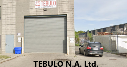
In 2008, Tebulo N.A. Ltd. was founded as a subsidiary to serve the North American market. Tebulo N.A. has operated under the mutual globally used trade name Tebulo Industrial Robotics since 2016.
At the start of 2020, we decided to sell this subsidiary as this would allow both companies more freedom to develop and grow independently. In this respect, as of January 2021 (the re-branding in Canada started this month), Tebulo N.A. Ltd cease the use of the ‘Tebulo’ name and will continue under a new name. To avoid any confusion and misunderstandings that may have arisen due to previous re-branding communication of Tebulo N.A., we would like to clarify the following:
In the near future, more updates will follow about our new product(s) development, newly explored markets, as well as the launch of a new website.
Due to recent economic developments, reshoring is trending. The need to bring back production activities forces us to find innovative ways to reduce operating costs, increase productivity and eliminate errors without compromising safety or quality. For the European market, we see a growing market triggered by the reshoring trend. These developments may seem challenging within your industry, but here at Tebulo Industrial Robotics, we believe we can help you achieve these goals. We’re looking forward to continuously assist you in improving your operations with our robotics solutions in years to come.
Stahl und Eisen, Nr. 1-2 | Januar-Februar 2022
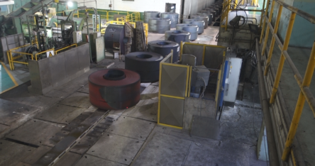
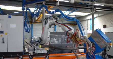
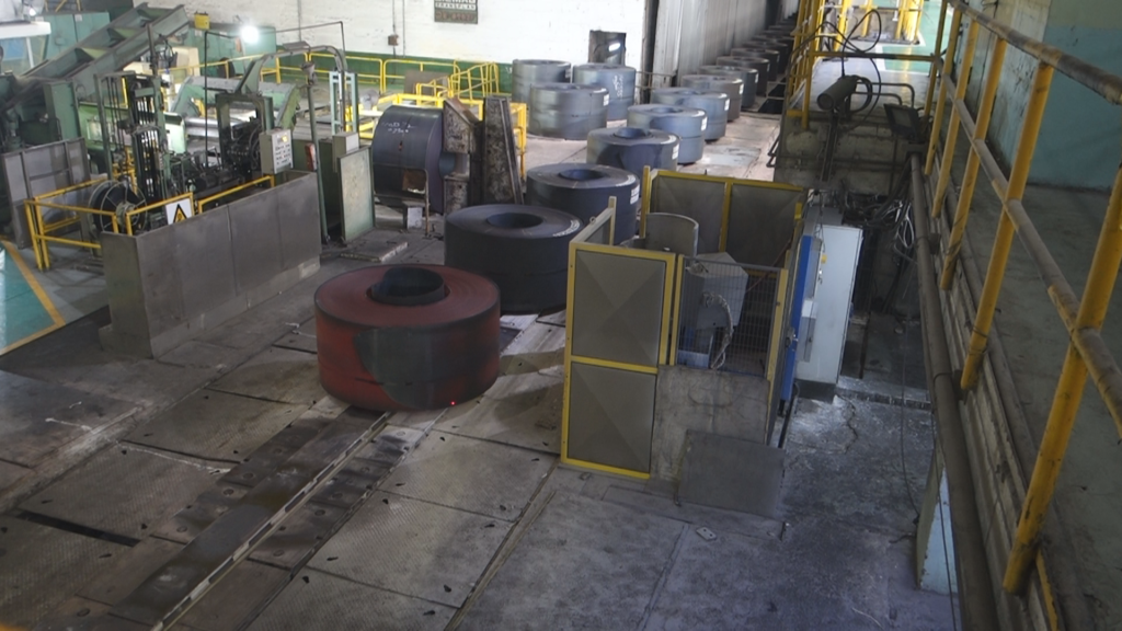
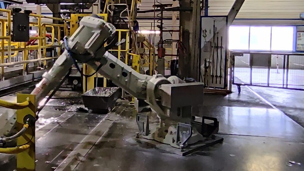
THAT’S WHAT IT’S ABOUT: The current production process entails pulling a preheated plate of steel through a 400- 500°C zinc bath. Operators must wear uncomfortable protective clothing, while manually scooping the dross from the bath in an extremely hot environment. It is a daily reoccurring and definitely unsafe situation, with all the risks that it entails. Particularly for such production environments, Tebulo Industrial Robotics has developed a robotic dross system with smart tools, which allows for easy implementation in any existing production process of galvanizing steel. Even with limited space.
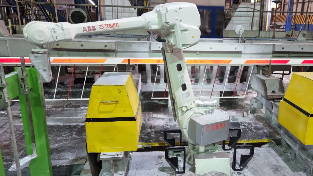
Providing 24/7 dross removal from both sides of the steel plates to prevent any contamination, while increasing the operators’ safety and ease and ensuring a continuous, high quality of galvanized steel plates.“ These were the main instructions for Tebulo Industrial Robotics regarding the development of the recently introduced dross-robotic system. This solution stands out since it may be integrated into any existing production process, in spite of tight space constraints. With the new installation, there is no longer any human interference. The manufacturer opted for an ‘out of the box’ solution with a front robot and a V-side robot, smart, user-friendly control software and a patented tool changer.
Process
In the continuous galvanizing process, a steel plate is fed through an inert nitrogen environment furnace minimizing exposure to oxygen and dipped directly into a zinc bath. The deflector roll submerged in the zinc bath deflects the plate and covered in a thin zinc layer on both sides leaves the bath were the air knives blow off excess zinc, leaving a wafer-thin zinc coating of a constant thickness. During zinc application, the steel plate is kept as stable as possible by means of stabilizers, correction rollers and/or stabilizing magnets. Under extreme conditions, operators must manually scoop the dross (read: contamination resulting from a chemical reaction) from the zinc bath during every shift. Hans Spaans, Technology Director with Tebulo Industrial Robotics explains: „Oftentimes this takes place just too late, causing dross accumulation and contamination on the steel plate. This compromises the steel plate’s corrosion resistance and negatively affects the finished product’s appearance, not to mention that it causes unsafe working conditions for the employees.“
Number of Robots
Dross removal may be carried out with 1, 2 or even several robots. It depends on various factors, such as the available space surrounding the steel plate, the desired end result, the process in the zinc bath and the available investment budget. Especially with existing zinc baths, the installation of two robots is already quite a challenge, since space is limited. Spaans: „Such a situation requires a creative and safe solution, so that the existing installation remains fully intact, while the use of robots allows for the most optimized processing. We realized this by suspending a V-side robot from a track (i.e.: a kind of overhead rail system) over the zinc bath. It was equipped with various tools and programmed to cooperate with the front-side robot.“
Suspended V-side Robot
The track from which the V-side robot is suspended was mounted to the furnace existing steel structure, allowing it to move from left to right and vice versa. To ensure the required rigidity in this construction, an additional gantry was added to support the track. The V-side robot works with two types of rakes on the steel plate’s rear (V-side) and ensures that the dross is offered in a controlled way in the front-side robot’s operational area, so that the latter can handle the dross-removal process from there. Both robots operate with an in house designed tool changer to ensure a maximum flexibility to select the tool made to measure for each individual project application to accomplish an optimized dross removal process. As mentioned above, we work with 2 types of rakes for the V-side robot and we utilize a total of 4 types of rakes and shovels for the front robot. Rob Beentjes, General Director of Tebulo Industrial Robotics adds: „It is important that the zinc bath be disturbed as little as possible to achieve the highest possible zinc quality. In other words, all necessary movements, such as raking and scooping out the dross, must be carried out as gently and efficiently as possible at all times.“
Tool Changer
Particularly noteworthy is the fully mechanically operated, patented tool changer system. This system consists of a tool station with individual rakes and/or shovels as well as a robot actuated tool changer (EOAT, End of Arm Tooling) with an ingenious attachment system. The entire tool changer system is suitable for the rough environment.
Spaans explains further: “Most of the tool changers on the market are pneumatically or electrically driven and therefore less suitable for use in heavy-duty environments contaminated by zinc dust. This is what prompted the idea to develop a suitable tool changing system of our own, where the robot with a robust gripper can fetch, return and secure the tools by itself. Thanks to the use of robotic movements additional cylinders and/or electric actuators are now superfluous. The result is a patented robust solution called the robot-actuated tool changer. The tool station is set up within the robot’s reach. As soon as the robot removes a tool, it is mechanically locked in place with the robust coupling mechanism, measured and calibrated. After use, the tool is replaced and unlocked. Says Beentjes: „Work is done with a unique pick-up and parking spot or a kind of key system, based on the Japanese poka-yoke system.“ In short: the key system is secured because each tool has a pick-up point with its own design. So it is impossible that tools end up in the wrong place when changing a tool. The tool assignment is constantly monitored by means of switches. Meanwhile, Tebulo Industrial Robotics has built and supplied a number of different tool stations for various applications worldwide.
Multifunctional Deployable
Aside from removing dross, the robot may also be used to carry out other types of work, such as cleaning the surroundings, placing or moving the 5-meter-wide safety fence, or taking zinc samples. Other attributes can be effortlessly attached to the robot, for example for sampling purposes. „The option to place (or move) the fence had already been incorporated within the initial robot design“, remembers Spaans. „Three positions in total have been set up where the fence may be placed. For example, the robot places the fence on the edge of the zinc pot during production when people want to enter the safety area (position 2). During the zinc pot’s change or in case of standstill the fence is positioned about one meter from the edge of the zinc pot to close the gap when zinc pot is removed (position 1). During production if there are no people in the robot’s working area, then it hangs the safety fence at the parking position (position 3) above the zinc bath. As with the tool change system described earlier, the ‘robot-actuated tool changer’ with additional double hooks and an adaptor plate on the safety fence is used to handle it properly and in a stable manner. The safety fence’s stability and its positioning are essential aspects when the robot hangs it up. So, it is interesting to note that the components’ shape is such that the fence automatically centres itself on pre-programmed positions, as soon as the robot places or removes it in a controlled manner.
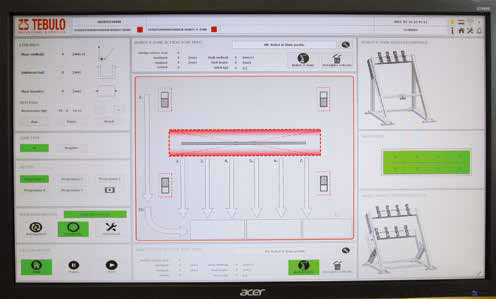
User-friendly HMI
For every zinc pot, Tebulo Industrial Robotics prepared in advance five different programs, so the most ideal movement procedure may be selected based on different process variables. For each program, robot movements are programmed in such a way that all corners and walls of the zinc pot are within reach of the specially manufactured tools. Control for each zinc pot program may subsequently be easily optimized via the advanced, extremely user- friendly HMI. Spaans explains: „In addition to the five automated cycles, it is also possible to manually set up one’s own cycle. For each of the pre-programmed options, the operator may first decide to play a video showing the movements the robot will make. As soon as the desired movements are discovered, the operator may activate the final selection.
Dross Bin
Next to the robot, in front of the zinc bath, the operator places an empty dross bin in a dedicated area in which all dross scooped from the zinc ends up. Once the (empty) dross bin is put in its place, the robot is able to detect and confirm its correct position and monitor filling level with the sensor integrated into the robot arm. When the dross bin is almost full, the sensor reports this to the HMI, so that the operator can replace the bin in time. Moreover, the dross bin level is displayed on the HMI.
Removable Front Robot In case the steel plate breaks, or if the operator needs more space during a stoppage, the front robot may simply be removed from its spot by a forklift. This creates a completely even (flush) floor area, free of trip hazards. Optionally, a winch drive may be set up in the free space to haul the steel plate back into position. Moreover, the free space may be utilised to safely perform necessary tasks for the zinc bath. Particularly with the option of removing or returning the robot, Tebulo Industrial Robotics produced an ingenious robot fastening construction allowing for continuous positioning accuracy.
All in All
The introduction of the aforementioned robotic dross removal system, has substantially improved the operators’ working conditions as well as the zinc plate’s quality. The above-mentioned development is extremely interesting for types of industry where continuous high product quality and operator safety are the absolute requirements.