Marker Robot Improves Product Performance

“A substantially higher production speed, as well as printing a marking of more characters on the flat and rounded sides of extremely hot rolls of steel, in less time”. Thus, the demands imposed by China’s leading steel producer when ordering the latest marker robot for their hot strip mill from Dutch manufacturing company, Tebulo Industrial Robotics. Or, in short: “Substantially improve the cycle time of our hot strip mill.” In this article, Hans Spaans, Technology Director of Tebulo Industrial Robotics, explains how he met this challenge in a country supplying 50% of the world’s total steel production.

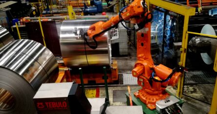
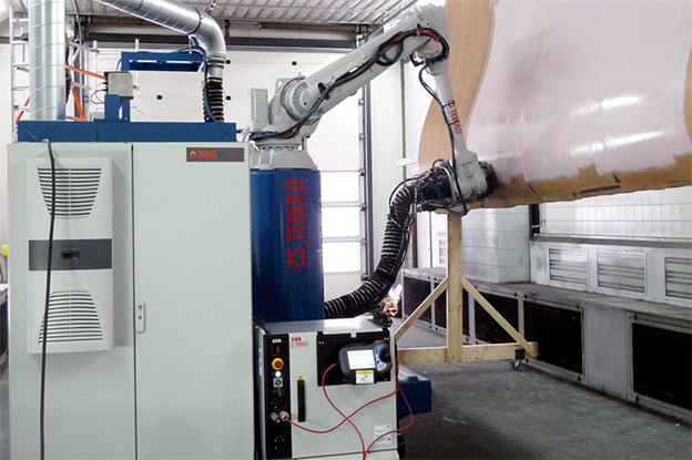
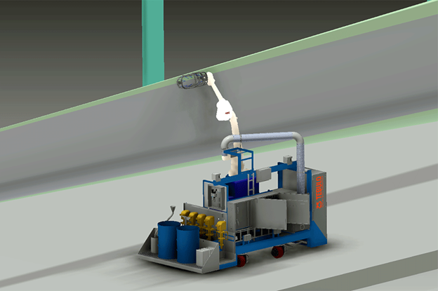
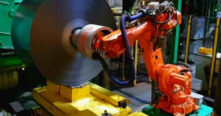
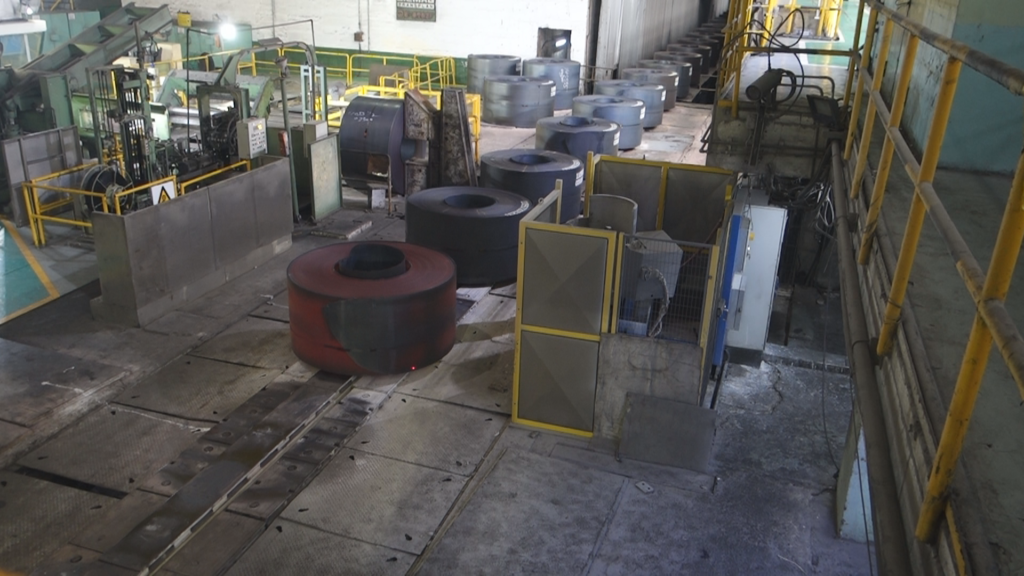
With considerable speed, approximately 60 glowing hot rolls of steel (800° C), weighing 20 to 30 tons each are passing through, with their ‘eye to the sky’, on the ‘walking beam’ in the Chinese hot strip mill. Positioned beside the ‘walking beam’ is Tebulo Industrial Robotics’ latest marker robot. Within the traceability context, this robot applies a unique ID number to each of the rolls. For several decades and to the fullest customer satisfaction, Tebulo Industrial Robotics delivered marker robots to the leading Chinese steel manufacturer, annually producing 21 million tons of steel.

For over 20 years, the above production line had operated with a Tebulo marker robot. Spaans explains: “However, the robot had reached its technological end of life and needed to be replaced, as spare parts were no longer available. So this was the main reason for ordering a new marker robot.”

Process

One by one, the robot prints markings on passing rolls, which appears simple. Yet, in practice it turns out to be a considerable technological challenge. Namely, on this production line, the exact position per roll is not defined: It is always an approximate position. Consequently there may be considerable variations in a roll’s position. Due to the extremely high temperatures and slight inaccuracies in the line’s drive system, the rolls of steel are not accurately positioned. As soon as the roll in need of marking stops, the robot must first detect where the marking should be placed on the roll’s side, as well as the roll’s exact position and height. In order to establish this, first a procedure to determine the accurate measurements must be carried out. Successfully performing the procedure constituted a major technological challenge, since it is all very time-critical.

Time

The cycle time per roll amounts to 60 seconds. Per roll, only 25 seconds are available for the application of the marking and the measuring procedure, while merely 15 seconds are utilized for the actual measuring. In other words, the unique ID number has to be applied in the 10 remaining seconds. Spaans explains: “This was hardly feasible for the old robot, let alone with the new one. The standard for the latest marker robot was, namely, that it had to have the capability to maximally apply 25 characters at a time. On average, the application of 1 character takes 1.2 seconds. The smaller characters still take 1 second per character. Once the walking beam stands still, the marking is applied. The line comes available as soon as the robot finishes its procedure. While intending to solve these technological challenges, the producer intended to increase line performance as well. In short: More had to be accomplished in less time. So we needed to find a different, smart solution.”

Previously

In the old process, the line control system determined when the rolls of steel were stopped. There were no line data, speed and position data available. So the robot’s controller received a start signal from the line controller as soon as the line stopped. Next, the robot controller received the printable data. Before the marking could be applied to the roll of steel, the robot arm moved towards the steel roll in order to measure the diameter, position and height of the roll in a fixed pattern. Next, based on all of these data, the controller could plot the robot’s exact trajectory needed for the application of the marking’s received number of characters. Spaans explains: “Elaborating upon the old system, we have sought for a way to gain time somewhere. The idea emerged to optimize the measuring cycle by conducting it while the rolls of steel were in transport. Also, whenever feasible, process time could be considerably shortened by performing various measurements simultaneously, instead of one by one.”
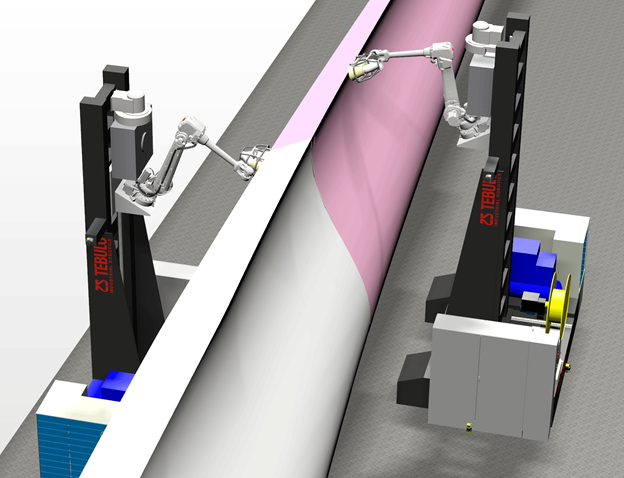
Measuring Process

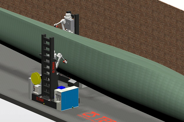
The measuring process consists of a combination of a distance laser and synchronization of line transport. Every 5 ms, the laser detects each roll’s contours by performing a distance measurement on the passing roll from a fixed position. The speed at which a steel roll passes is determined by accurately measuring the line movement with the assistance of the line transport sensors. By combining data derived from both measurements, the respective roll’s contours may be determined, as well as its exact stop position. Next, these data are sent to the robot controller which combines these data with the fixed, known distance to the walking beam, in order to calculate the roll’s position and particularly the location of the arch on which the marking needs to be applied. Moreover, the known information is that the rolls are accurately positioned within +/- 200 mm. The rolls are perpendicularly placed on the line by means of a tilting system with an allowable positioning accuracy of +/- 150 mm. In other words, based on the available information, the robot’s controller easily plots the exact trajectory in which the marking needs to be applied. No additional measuring is required in the described approach, aside from the roll-height measurement, saving approximately 10 seconds per roll. When asked whether the height measurement might also be included in one pass, Spaans responds: “No, a height measuring process is necessary under all circumstances. This is because not all rolls of steel are identical, while the marking position, as seen from the top down, must always be identical. The height measurement also helps to determine whether the roll has a case of telescoping. This measurement performed on the roll’s flat side is a tested and approved measuring approach. In a case of excessive telescoping  the marking is only printed on the roll’s rounded side.

Single Nozzle

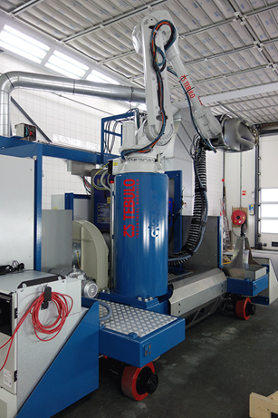
On average, every 3 to 6 weeks, during a regular maintenance stop, the robot receives any necessary maintenance. If the rollers of the hot strip mill have to be replaced, then the line with the rolls of steel needs to be emptied. Consequently, the line transport speed changes. In the controller’s new configuration, this does not at all impact measurement accuracy. Just as previously, the customer decided again for a single nozzle for the latest marker robot. A seven-nozzle dot matrix is faster in applying a marking. However, the single-nozzle design is much less sensitive to pollution within a hot environment, so it has a better performance output than the dot matrix. The white paint utilised for the marking’s application was fully developed in-house by Tebulo Industrial Robotics. The paint can easily be refilled while the robot is in operation, since the paint supply system sits outside the safety fence surrounding the robot.

Finally

Concluding, Spaans says: “Meanwhile, Tebulo Industrial Robotics has placed several marker robots, as described above, in hot strip mills worldwide. We were able to accomplish a considerable time savings per roll, particularly by integrating data from line and robot control in conjunction with parallel implementation of various measurements. This benefits the line’s eventual performance as well as TCO.”

Exclusive: Robot trial looks to speed up production for large wind turbine blades

5 February 2021 by Eize de Vries, Windpower Monthly

Dutch firm TebuloRobotics hopes its autonomous mobile robot (AMR) vehicles will be able to coat a 100-metre blade in 90 minutes. All they need is a smooth, obstacle-free factory floor

TebuloRobotics’ scaled AMR vehicle during the blade coating demonstration

As rotor blades get ever longer, manufacturers are looking for ways to automate the still many manual steps involved in their serial production. Dutch high-tech industry solutions developer and equipment supplier TebuloRobotics recently gave a precision blade coating demonstration of their latest autonomous mobile robot (AMR) vehicle designed with this in mind.

During the demonstration with a short-straight-scaled blade section, each time the AMR completed a partial coating task, it would move autonomously to a new predetermined position, temporarily lock its wheels before working on the new section and then move on again.

Multi-purpose tool carrier

The AMR’s four electrically driven 360-degree rotatable wheels allow it to move precisely and without restrictions in all directions. The vehicle further incorporates many other innovative features, including cutting-edge external guided motion (EGM) technology for following complex three-dimensional turbine-blade shapes and curvatures, without requiring detailed product dimensioning to be pre-programmed into the robot.

“The AMR, being functionally a multi-purpose tool carrier, carries all its necessary supplies like paint containers in blade-coating application mode,” explains Hans Spaans, technical director at TebuloRobotics. “It also incorporates all computerised industrial PC and programmable logic controller (IPC/PLC)-based controls to enable the vehicle’s own autonomous movements and to operate the industrial ABB robot plus application device(s) for conducting specific tasks.”

To perform precision coating of a blade, the advanced spray head developed by Dutch start-up Qlayers is attached to the robot’s arm. Additional integrated support systems include a surplus-paint-particle removal provision with built-in suction and cleaning filter units, all incorporated within the carrier vehicle. “Cleaned” air is then released again in the coating space through vents in the vehicle’s bottom section.

Following the successful proof-of-concept test of the scaled demonstrator (right) with a 3.5-metre vertical reach at a rented facility near Leiden, the Netherlands, the hi-tech unit will be shipped at short notice to an unnamed customer working towards the anticipated full-scale product launch — with a reach of 8 metres — this summer.

Here it will perform a series of trials to demonstrate the AMR’s capabilities and potential as a major leap forward in automating processes requiring high levels of precision, which are currently done manually during rotor-blade serial production.

Such automation is widely considered an essential precondition for efficient, cost-effective blade manufacturing as suppliers look to increase production volumes as well as accommodate continuous incremental size increases — with the latest onshore blades now reaching 80-85-metre-plus lengths and next-generation offshore models at 100-115-plus metres.

The next envisaged step, after completing these demonstration and validation trials, is building a full-scale AMR developed along the same main principles, says Spaans. “Our goal is to complete this full programme until the product’s launch within the next six months,” he adds.

Deployment options

“One of the product’s key characteristics is to make it highly flexible for autonomously performing multiple, automated tasks in different industries, including wind. It could carry out multiple processes during typical rotor-blade production, at different manufacturing stages.”

Spaans lists some examples for potential AMR-deployment:

The AMR could, for instance, autonomously apply glue all along the edges of one shell before a blade mould containing two shells and all internal components is closed. After the cured blade has been taken from the mould, the carrier vehicle could be redeployed for deburring the blade seams with an electrical cutting tool mounted to the robot arm.

Potential additional AMR usages include:

  • non-destructive inspections of blades’ laminate;
  • surface grinding and cleaning;
  • precision coating and polishing;
  • and attaching add-on features, such as vortex generators and trailing-edge serrations.
The AMRs could also perform tasks such as surface sanding or polishing

Pieter Oord, TebuloRobotics’ business developer, gives some more insights into the inner workings of the in-house developed and built AMR. “The vehicle has two built-in sensors to control the precision movement, including to predetermine logical pathway and real-time position coordinates,” he said. “They also check the required precise distances to a specific object, like the blade surface, along the longitude axis and relative to the blade surface. A great overall benefit of AMR-type systems is their built-in capability for achieving high accuracy levels by using EGM technology.”

For this EGM-enabled control, up to four additional positioning sensors are integrated into the robot’s head to accurately steer and control the movements of the ABB robot arms with a dedicated application tool.

Matchmaker

ABB Robotics sales engineer Martijn Dubbelman is the matchmaker who connected TebuloRobotics and Qlayers about two years ago for this ambitious project. He recalls how it started: “We already had an excellent professional relationship with TebuloRobotics, having cooperated on many projects over 25 years, and saw opportunities for teaming up with these two hi-tech companies. Wind-turbine rotor blades are a key example where advanced automation can offer huge potential, especially when combined with AMR deployment.”

These blades are large-scale structures characterised by complex three-dimensional shapes and curvatures and continuing to grow in size. This combination of factors was the main reason ABB Robotics thought it worth investigating how the three companies could jointly create added value.

Main challenges

Developing the AMR to carry out robotised coating and other complex application activities involving the latest and largest rotor blades of 100 metres or more brought some major challenges, as Spaans recalls.

“We used a generic 100-metre reference blade for our system modelling and AMR design input, with a 6-metre-range chord length [largest width] and around 7-metre pre-coning. Another key factor that needed addressing is the blade’s unavoidable sagging behaviour due to its own length and mass.” As a result, the built-in sensors recognise the position of a surface to be processed in real time. This means changes in object position resulting from structure sagging or other factors are no longer a problem, unlike in a conventional “rigid” system layout.

TebuloRobotics’ design team initially looked into such conventional guided-rail or gantry-type solutions for industrial robots or robot-mounting. However, both options ultimately lacked the flexibility necessary for performing the complex tasks and were abandoned. The decision was made to focus on AMR-technology, which has the huge added benefit to be capable of moving and operating fully autonomously. All it requires is a relatively smooth factory floor without obstacles, and no other modifications to an existing “conventional” blade production plant are necessary.

Oord says: “The fully automated, autonomous operating mode enables the AMR to ‘search’ for a specific blade to be coated, grinded or whatever, with all the main object parameters already stored inside the unit and ready for use. It does not need specific aerodynamic blade design input for a dedicated task, and there is also no need to accurately place an object in a given physical space like a spraying hall. This is because the sensor-controlled AMR-positioning robot, in combination with up to six sensors, automatically recognises the ‘wanted’ object and all relevant parameters, including curvatures and distances to specific surfaces. The AMR-system then performs a given task.”

Programmed to be versatile

Another key factor and main development challenge is that 99% of all robots deployed in industry are “hard programmed”. This means they are “fit” to carry out specific, repetitive operational tasks, and they do this typically within 0.02mm positioning accuracy range.

The AMR and application devices such as the precision coating tool must also operate within a high-accuracy range. In addition, it requires advanced dedicated robot programming to perform time-specific movements and tasks in different physical locations. This is why TebuloRobotics developed a new set of software-based AMR tools and controls, a process that continues for further matching and integration with various application devices.

Spaans hopes a full-scale AMR could be implemented in about one year after the coating demonstrator trials have been successfully completed and the client has given the green light.

“To perform all envisaged tasks with the latest generation large-scale rotor blades, this 1:1 scale AMR requires a much larger reach, so that it can cover 6-7 metre vertical distances, along the blade aerofoil from top to bottom, for example. The enabling feature for this is a vertical guiding beam for the integrated positioning robot, which can move up and down over the full processing distance,” he explains.

For specific coating tasks, the blade is positioned with the rounded leading pointing downward and the trailing edge with semi-standard flat-back aerofoil facing upward.

AMRs working in tandem

An optimised layout for workflow requires two AMRs per blade, one on each side, but there could logically be different configurations for other specific tasks.

Blade coating should ideally start at the blade root section, Oord suggests, with each AMR moving in predefined steps towards the blade tip. Calculations indicate that two AMRs could coat a complete 100- metre blade in about 1.5 hours, or three hours net when both a primer and closing top layer are applied. With the possibility of future single-coating solutions available, coating time would obviously be halved.

“The combination of our AMR-technology with dedicated partner technologies has the full potential to transform traditional — and to a substantial degree still manual —manufacturing practice into fully controlled, efficient, safe industrial processes. This is achieved with unparalleled accuracy and without requiring detailed product dimensioning or any specific infrastructural provisions, except a smooth, level floor space. We are positive that our fully modular scalable AMR-concept designed as universal tool carrier could provide a boost in automating other essential wind turbine manufacturing tasks and processes as well”, Oord concludes. 

Article Windpower Monthly: https://www.windpowermonthly.com/article/1706644/exclusive-robot-trial-looks-speed-production-large-wind-turbine-blades