Reel hole fixation robot reduces handling
For cold coiled steel coils with material thicknesses ranging from 0.13 to 0.5 mm, the inner flap regularly drops down when it comes off the mandrel in a steel shop. And even during handling there is a considerable risk that the entire coil will collapse. This is due to insufficient internal stiffness of the coils. In the former situation, a flap that drops down must be welded or glued manually by the operator, in a relatively unsafe manner. In the latter situation, a coil weighing 30 tonnes has to be removed, because it can no longer be placed back on a mandrel. Backed by a successful feasibility study, this constituted a sufficient reason for Tebulo Industrial Robotics to engineer a new reel-hole fixation robot for the steel industry.
Contrary to the traditional solution, the robotised solution now coils the material directly onto the mandrel, so the production process may continue without unnecessary interruptions. Consequently, the 8 to 10 mm thick steel sleeves– which were traditionally pushed over the mandrel before the material could be coiled up–are no longer necessary. This makes a substantial difference in man hours and handling costs. The sleeves no longer need to be transported from one location to another. Moreover, sleeves are no longer dropped and/or deformed. There is also no longer a need to reserve storage space in a warehouse or at the mandrel.

Principles
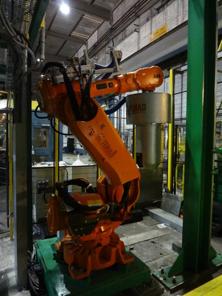
„In developing of the head for the reel hole fixation robot, we were intensely focussed on reducing storage, handling, as well as material costs. It was also essential that the payback time was less than 1.5 years,” says Hans Spaans, CTO of Tebulo Industrial Robotics. Based on the above requirements, Tebulo Industrial Robotics, took a standard ABB robot and converted it into a new tool, with welding functionality completely tailored to this purpose. The welding tool is designed for sheets with a thickness ranging from 0.13 to 0.5 mm. The average welding depth varies from 2-3 mm (approximately 10 wraps). The number of spot welds and the welding depth together provide reinforcement of the reel hole. As in the procedure with the sleeves described above, with the newly developed robotised solution the last 10 to 15 metres of material can not be used and should therefore be disposed of as scrap.
Welding Method
„In this case, traditional spot welding was not an option, since there was no possibility to reach the back of the material. That’s why we opted for twin spot welding,” says Spaans. The twin spot welder integrated in the new robot head, consists of a welding tool with 4 welding tips (two on one side and two on the other) in conjunction with an ‘intelligently’ working pressure mechanism. The chosen welding method requires a great amount of power, so in the robot head four 40 mm thick copper, hollow water-cooled cables run from the transformer to the welding tips. The transformer is powered by a control unit located in the background. As soon as the desired welding program is entered on this unit, a low voltage and a high current runs from the transformer to the individual welding tips, generating a medium high frequency welding current for the electrical welding process. Welding occurs with a pulsation frequency between 1000 and 4000 Hz. At the part undergoing plastic deformation, temperatures may increase to 1200-1400 ° C, whereas the cooling water temperature in the 20 litre capacity unit reaches 60° C. The water in this closed loop circuit cools the welding transformer, the head cables as well as the two welding tips. So it is essential that the recycled water is constantly cooled in the heat exchanger during the welding process.”
Flap Detection
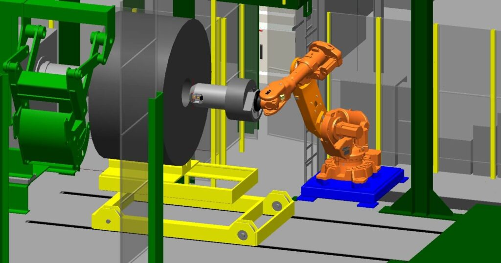
Another important design requirement was the robot head’s compact design. The robot head must always be able to enter the reel hole, without getting stuck anywhere, even when a particular flap is hanging loose. Spaans: „A coil of steel always has a 420 mm reel hole diameter. So in the design phase it was decided to maintain a minimum free passage of 340 mm for the robot head. In the available space, the head must be able to scan and weld a 360° area without any complications. The scan data are communicated to a PLC. Having made a successful scan, the entire robot head retracts and the robot takes up its starting position. Next, the PLC calculates where the robot head should start applying the first welds. We opted for a 180° rotation range because of the large number of continuously rotating (power) cables, water and pneumatic hoses. The robot head is therefore equipped with a double set of welding tips at 180° relative to each other, achieving in all cases a 360° range.”
Welding Process
The PLC then determines the exact location to start welding as well as the welding pattern, communicating the data with the line control. Next, the robot head starts out by firmly pressing the flap outwards, against the inside of the coil, creating a nice round hole. Especially for this purpose, the robot head comes equipped with a pneumatically driven cylinder with a 160 mm stroke length which pushes out two pressure blocks. The four welding tips then move alternately. Based on the transition resistance caused by several layers of material, welding requires a pressure of approximately 450 kilograms. This is achieved by two pneumatically driven cylinders, each with a 30 mm stroke length. During the application of the first welds, the coil is still half situated on the reel, ensuring the flap cannot drop inside. Upon completion of the the welding, the coil is completely removed off the reel, so that the production process may continue. Moreover, the robot can also access the coil of steel from the other side to fully strengthen the inside, 20 to 30 seconds after it has finally been completely removed from the reel. In this way, with the help of the aforementioned welding tool the coil’s own material is utilised to create a sleeve inside of the reel hole. Spaans explains: „Particularly, the detection of the beginning of the flap, and the calculation of where the first spot weld must be placed is a precision job. If the first weld is placed incorrectly, then the inner wrap pulls apart during hoisting which must be avoided at all cost.”
Operation
Depending on the processed material thickness, the selection of the correct welding parameters is initiated. During welding, it is then measured whether the current flows through or not. If the current does not flow properly, for example because the copper points are not properly pressed, this is immediately detected by a sensor which sends a feedback signal to the PLC. The correct pressure, clean pressing material, good components and a properly functioning electronic feedback system are all essential for a good weld.
Capacity
The production line, with the currently successfully running robotised welding installation, has a capacity of approximately 400 coils per week. The steel coil stays on the reel for an average of 20 to 30 seconds during the first stage of the welding process. As soon as the coil has come off the reel, it is no longer time critical at all. This leaves the robot with about 15 minutes to perform the remaining activities. In other words: Flap detection as well as producing the first welds in particular should be carried out as quickly as possible. Spaans explains: „The biggest challenge in the development of the above-mentioned robot head was to find an optimal balance between transformer, power supply, cable diameter and reel hole size. For example, 450 kilograms of pressure had to be applied in an extremely small diameter reel hole, while the robot head had to be as compact and light as possible. After all, the robot also had to be able to handle the head over a larger distance. From a safety point of view, we opted for pneumatics instead of hydraulics for the welding tool’s drive technology, since the risk of potential oil leakage was undesirable.”
Finally
The reel hole fixation robot described above can also be used for aluminium coils. Says Spaans: „Since there are so many different types of aluminium, the correct parameter set must first be determined for each type”. Finally, it is worth mentioning that the robot needs a floor space of approximately 3×3 metres, within which it can operate the so-called ‘safe move’. As soon as the robot arm detects interference with the imposed restrictions, it is fully automatically limited by the built-in safety contcoiler, which closely monitors all of its movements. Safety first,” says Spaans.